- If you are sourcing your own parts, you need to build the switch/battery connector assembly. For diagrams see Vorpal Combat Hexapod Battery/Switch Construction.
- Also see important information on that page if you are sourcing your own BEC.
- If you are sourcing your own Bluetooth modules, please be aware that you will need to configure them to auto-pair and to have a UART speed of 38400 BAUD. Every module brand is a bit different so it's not possible for us to give you universal instructions on how to program them. We assume that if you source your own parts you are familiar with how to configure Bluetooth modules using AT-commands.
ROBOT BOM

- Electronics:
- Passive Piezo Buzzer module and 3 wire cable (see image)
Passive Piezo Buzzer Module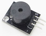
- 1 x Chassis
- 1 x Cap
- 6 x Legs (individually marked with servo numbers)
- 1 x Switch adapter
- 12 x Servo bracket U-shaped halves
- 1 x Electronics Caddy
- 1 x Stand
- 1 x Eye/glasses Decoration
- 1 x Joust game accessory with "rider"
- 1 x Capture the Flag game accessory with flag and cup.
- 1 x Fidget Spinner Challenge game accessory (no Fidget Spinner, just the stand)
- 1 x Ultrasonic Rangefinder Bracket
- 9 x 10mm diameter pairs of hook and loop self-stick circular dots. These go on the hexapod cap (hook) and accessories like eyes and nameplates (loop).
- 7 x 10mm diameter by 3mm thick ceramic magnet, north pole marked. These are for Capture-the-Flag and Joust accessories. (Note: Not included in Bare Bones kit).
- 12 x socket head cap screw, 2.5mm diameter by 8mm long (for servo horns)
- 3 x #6-32 x 1/2" screw to fasten on/off switch adapter (2) and to hold electronics caddy on chassis (3)
- 2 x #6-32 x 3/4" screw for bottom two holes in accessory port.
- 2 x #6-32 x 1/2" screw for top two holes in the accessory port.
- 4 x #6-32 nuts to hold screws in accessory port.
- 2 x #6-32 wingnuts to attach accessories to accessory port.
- 1 x L shaped hex driver, 2mm, for both kinds of screw used in the kit.
GAMEPAD BOM
- Electronics:
- 1 x Battery/Switch Wiring Unit with 9v battery clip. (Note: the gamepad requires no BEC so you can use this fact to distinguish from the robot wiring unit)
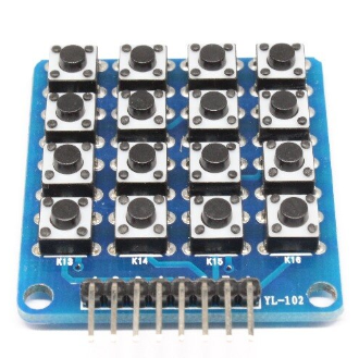
- 1 x 4x4 button matrix with associated connecting wires. The matrix we use is marked YL-102 in the corner. See the picture. It's blue and has the keys number K1 through K16. You may be able to use others but the pin numbers may differ.

- 1 x Gamepad base plastic part
- 1 x Gamepad top plastic part
- 1 x Gamepad button carrier
- NOTE: Gamepad Base versions before April 2018 also required 1 x Switch Adapter
- 4 x #6-32 x 1/2" screw to hold cover on gamepad (4) and also to hold switch adapter on base (2)
- NOTE: Gamepad Base versions before April 2018 also required 2 more of these screws to hold on the switch adapter.
Sensors
These are included in the Deluxe version of our kit. They're mainly useful for Scratch programming activities.
- 1 x HCSR04 Ultrasonic Rangefinder
- 1 x Analog Light sensor
- 1 x 30cm USB cord type A to mini
3D Printing the Plastic Parts
Obtaining the STL Files
You can find all the current STL files here: VORPAL FILES. Go to the STL folder. The Vorpal Hexapod STLs are in the subfolder ROBOT and the gamepad parts are in GAMEPAD. There are subfolders with accessories (such as sensor housings and game pieces).
Printing Notes and Tips
This project has been finely tuned to make it easy to 3D print. No supports are required for any of the parts. In some cases you may want to use brims or rafts to help parts adhere to the print surface. There is minimal bridging, never farther than about 15mm (5/8"). Some of the parts do require some flexibility, for example the sides of the servo compartments need to bend outward while the servos are inserted, they then snap back into place when the servo is completely inserted. This means brittle plastics like PLA are not the best choice for this project. (Although we have made PLA hexapods and they do work if you're careful when inserting the servos).
This page assumes you have basic familiarity with 3D printing and 3D printing terminology. If not, you might want to reference online materials such as youtube videos or information from your 3D printer manufacturer before attempting this project.
If you are 3D printing the plastic parts (as opposed to buying them pre-printed), here are some tips.
- MINIMUM PRINTER REQUIREMENTS
- The bed size should be at least 150mm cube (5.9 inches cube). The largest part is the hexapod base so it is the limiting factor on bed size.
- A heated bed is strongly recommended, especially if you are printing in ABS.
- ABS and PETG both work well. When we sell Full Kits and Assembled Vorpals we use ABS.
- PLA is somewhat brittle, but it will work if you're careful. Inserting the servos into the legs and hips will somewhat flex the plastic so be careful during that process with PLA. Attaching the two halves of the leg hinges together can be more successful in PLA if you first soak the hinges in very hot tap water to soften up the plastic a bit.
- 0.38 layer thickness (or whatever layer thickness is optimal for your printer)
- 1mm walls (i.e. two perimeters)
- 1.14mm top and bottom (i.e. three layers)
- 15% infill
- You can print with thinner layers if your printer does not support 0.38mm layers or if you want a more refined look, it will just take longer.
- Brims or rafts are recommended for the following hexapod parts: Base, Legs, Electronics Caddy, Cap. This ensures proper bed retention to avoid warping. These parts have relatively little contact area with the print bed, or have certain sections with little contact.
- Brims/rafts are not recommended on any of the other parts. The other parts generally have enough bed surface contact that they will print fine without brims. Your mileage may vary however and it is recommended that you keep a close eye on the first few layers of the print to make sure everything is sticking properly. If not, you can cancel the job with minimal loss of plastic then restart with brims or rafts.
- We personally prefer brims (such as available in Cura) as they are easy to remove and leave a clean look.
- Other than removing brims/rafts and the occasional drip, there is not any special post-processing required after printing.
- However, be very careful to inspect the hemispheres jutting out of one side of each of the servo holders, these need to be as low friction as possible. Inspect for drips and defects. If necessary, use a file or sand paper to smooth them out.
Building the Robot
You will need the following tools:
- 2mm hex key. A 5/64 inch hex key will also work. This is in the Hexapod Parts bag. (NOTE: Some very early kits put this in the Deluxe Parts Bag).
- A marker that can write on dark plastic and still be seen, such as Sharpie Metallic or Sharpie Oil markers (white and yellow work great).
- This is the easiest way to mark servo wires with their corresponding leg number
- If you don't have these types of marker, you could use clear tape and bits of paper to tape wire labels near the socket end of the servo cable. Don't put labels right on the black plastic connectors at the end of the servo because you'll make them too thick to fit side by side when plugged in.
Servo Pre Check
Sometimes the servo motor gearbox will get locked up when sitting for a long time, for example during shipping, especially in cold weather. The following procedure will ensure they work properly. (Note: Some MG90S servo bags distributed in the past with our kits say not to turn the servo horn, these instructions supercede that note on the bag).
- Put a one-arm servo horn on each servo. You don't need a screw, just put it on in any random position for now.
- Slowly and gently rock the servo horn by hand so it turns. Do not use a lot of force. Note that there is a physical stop that only allows it to turn 180 degrees. If you push in one direction and it won't move, rock it in the other direction.
- As soon as it moves, even just 10 or 20 degrees in either direction, you've confirmed the servo is not locked. Do not leave it at an extreme position where it stops, leave it somewhere around the middle.
If any servo fails to move with modest pressure and a gentle rocking motion, put a mark on that servo, near where the wire comes out. It will most likely unfreeze when power is applied, but you need to keep an eye on it for now.
Step by Step Instructions
- STEP 1: Insert accessory port screws in the chassis Insert 5/8" #6-32 hex head screws in the bottom two holes of the accessory port, head of the screw inside the hexapod, then tighten nuts outside. Repeat for the top two accessory holes with shorter 1/2" #6-32 hex head screws. The heads of the screws recess into hexogonal holes so you don't need to use pliers inside the robot body, just for the nuts. Two wingnuts go on the two lower screws, these will be used to secure accessories such as the Joust lance or Capture-the-Flag attachment.
Be sure to use the hex head screws for the accessory port.
The accessory port is considered the "front" of the robot.
Longer hex head screws go on the bottom. Do not overtighten the nuts.

After installing the nuts, put the wingnuts on the bottom screws. They'll be used later to secure accessories.
- STEP 2: Insert servos in the chassis.
- Next, insert the servo into the chassis as shown in the diagrams below. As you insert the servo into the chassis, slowly press it straight into place until it clicks in under the small tab on one side of the servo holder. Make sure it stays straight as you push down.
- Immediately mark the black connector at the end of the wire to indicate the servo number (which is engraved in the top of the servo holder, a number between 0 and 5).
- A metallic sharpie pen works very well for this, or a light colored oil paint sharpie such as white.
- If you don't have any of those things, a little piece of masking tape can be affixed to the wire and marked, or you could use clear cellophane tape to attach little bits of marked paper to the wire. Do not attach any tape or paper to the black connector, as it will be a tight fit when connecting later.
- The wire coming out of the servo sticks out away from the robot, the servo shaft would face down toward the table top if the chassis were resting on the table.

- STEP 3: Insert the servos in the Legs. The technique is very similar to inserting the servo into the chassis.
- Insert the servo straight into the leg socket so that the wire is coming out of the servo facing away from the plastic leg and the face of the servo with the shaft and servo horn goes into the open faced side of the leg, as shown in the diagram.
- The servos in the legs are called the "knee" servos. Each leg has a higher number on it, this is the knee number, they run from 6 to 11. Again, write this number on the black connector at the end of the servo wire. PRO TIP: For 6 and 9, underline the number so you don't read them upside down!

- STEP 4: Thread each leg servo wire into the bottom wire guide slot on the chassis. Each leg servo should be matched with a hip servo plus 6. The legs are marked with the hip number near the top and the knee number below that. For example, the leg marked 6 should be threaded through the wire guide on hip servo 0, leg 7 goes with hip 1, leg 8 goes with hip 2, etc. Add 6 to the hip number to get the leg number.
- STEP 5: Build the electrical system. You need to power up the servos and make them seek to the 90 degree position, this will allow you to adjust the legs properly for walking.
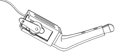
- STEP 5A: Take the potentiometer and remove the cap, then unscrew the nut and set these items aside for now. Push the potentiometer shaft from the inside of the chassis, into the hole that has the markings "STOP", "TST", etc. The wires coming out of the potentiometer should be pointing down and you may need to bend them a bit to make it all fit. Put the retaining nut on the potentiometer, hand tighten first and then give it just another half turn or so with pliers if desired. Turn the knob all the way counter clockwise, then insert the knob so it points to the letter "O" in the word "STOP".
- STEP 5B: Find the on/off switch (which is attached to the battery holder assembly). There was a change to how this was installed in October, 2019. The older version requires a "switch adapter," while the new version just uses a slot to feed in the wires. The two sets of diagrams below illustrate both the old and the new way of installing the switch.
New Version Switch Installation:
Thread the switch and its wires through the Base, there is an opening under the switch hole.
Bring the wires up through the slot below the switch hole.
Press the switch into the hole, it should snap into place. The "1" should be on top.
Old Version Switch Installation (before about mid October 2019):
Thread the wires through the gap in the adapter
Press the switch into the adapter.
From the inside of the robot, line up the switch/adapter with the switch hole.
While holding the switch/adapter in place, insert screws from the outside of the robot.
- STEP 5C: If you do not have a "QuickBuild" version of the kit, then make all the connections listed in the ELECTRICAL CONNECTIONS section of these instructions below. Be extremely careful about the power connections. Double check all connections before powering on. If you do have a QuickBuild kit, all the connections are already made for you.
The servo horn should come straight out from the body at a 90 degree angle as shown here. Do not turn the servo shaft by hand until after it has moved under power!
- STEP 6: Power up! Make sure the on/off switch is off, and the knob is turned to STOP. Insert batteries and power on the robot using the on/off switch. You should hear a beep, a pause, then a second beep. The servos should all twitch into position. If the robot does not move at all, immediately turn the switch off and check your connections again. If some of the servos don't move (especially any you marked during the servo pre-check) then gently push them with power off to see if you can free them up. If they still won't move, try pushing them with power applied, but turn off the power within 30 seconds if they're locked up. If you can't get the servo to move it will need to be replaced.
- STEP 7: Insert Servo Horns. The servo horns are all at random angles right now due to the servo pre-check. In this step we'll make them point in the right direction. The knee servos are not at 90 degrees when the knob is all the way counter clockwise, rather they are at a 30 degree standing angle. We need to get them to 90 degrees so its easy to align the servo horn. Turn the knob very slightly clockwise and you will see all the knee servos twitch. This is "adjust servo horn mode". All servos (knees and hips) are now at their halfway point, 90 degrees. Now you need to take each single arm servo horn and carefully insert it on the shaft so that it is sticking straight out as shown in the figure. You will not always be able to make the horn come totally straight out. This is because there are only 22 little groves (splines) in each shaft, meaning you can in general only come within about 8 degrees of being at a perfect 90 degree angle. This amount of error is acceptable, just get it as close as you can. It is better for the horn to be a little too much clockwise than to be a little too much counterclockwise, especially for the knees. Do this for all hip and knee servos. Do not insert any screws yet.

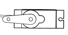
Align the leg hinges as shown here. The bumps (see arrows) should both be near each other when properly aligned. Hold one in each hand with the ends of the U shape between thumb and forefinger.
- STEP 8: Assemble the leg hinges. Each leg hinge is composed of two identical U-shaped parts. Take one in each hand and align the two so that the bump (shown in the diagram at the right) are both near each other. Turn one 90 degrees with respect to the other.
- Gently squeeze each piece between thumb and forefinger, which causes the little jaws in the center to open up slightly. Work the two halves together. Squeeze just enough so they work their way on, no more or you might break the part!.
- At this stage, you may notice that the parts are loosely clamped on each other. Don't worry! When you place the leg hinges over a servo, the servo will spread it apart and they will lock together tightly.
- NOTE: It should not be excessively difficult to push the hinge over the hemispherical bearing. If you find you are struggling, that means the hinges are too tight. This may affect walking. This can be due to the kind of plastic you used or how your printer is adjusted. You may need to gently spread the two legs of the U shape by hand before putting the hinge on the robot. Be careful of course not to break the hinge.
- STEP 13: Test Using Demo Mode. Ok, everything looks good, so time for a full test. Turn the knob to STOP, then take the robot off the stand and put it on the floor. Turn the knob to DEMO, and the robot will go through a series of movements to demonstrate some of the things it can do. The full demo only takes about 30 seconds, then repeats. Here, you are looking for the robot to, for example, be able to get back up off the floor after doing some of its dance moves. If the robot struggles to get off the floor, you may have a battery that is not fully charged, or there may be too much friction between the servo bracket and the little ball socket it sits in. A tiny bit of silicone lubricant will usually fix that problem, or just make sure those parts are cleaned up from 3D printing and don't have an excess strands of material that are causing friction. See the Trouble Shooting Guide for more information about different kinds of issues that can occur.
- STEP 14: Store the Electronics in the Caddy Now things look pretty messy with all those wires hanging loose, let's clean it up by stowing them in the electronics caddy. Please reference the video and diagrams here for quick instructions.
- STEP 14A: Insert Caddy Bars Insert the two electronics caddy bars as shown in the diagrams below. Notice carefully how they are inserted. You may need to slightly squeeze the forked section at the end to work it into the hole. Once inside, it may be difficult to remove because it will snap into place, so be sure you're putting it in the right way.

Here one bar has already been inserted, the other is being put into place. Notice the orientation, don't put it in upside down. The little nubs at the end should be facing the caddy.
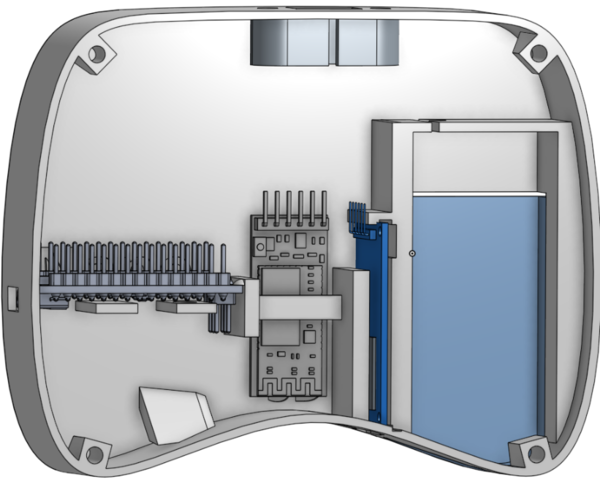
- STEP 14B: Insert the Servo Controller and Arduino Nano The diagrams here do not show the wires to make them easier to visualize. Carefully insert the servo controller as shown, making sure you don't pull out any of the wires. You may need to wiggle the electronics caddy bar from side to side a bit so that components can slide past it during insertion. Notice that the end of the Servo controller with wires sticking out of it must go in last. Carefully insert the Arduino Nano as shown, making sure you don't pull out any of the wires. You may need to wiggle the electronics caddy bar from side to side a bit so that components can slide past it during insertion. Notice that the end of the Nano that has the USB port must go in last.

Insert the servo controller so it is sandwiched between the bar and the electronics caddy. Wires not shown for clarity.

Insert the Nano so that the USB port faces out away from the electronics caddy, this allows you to access it without disassembling the robot.

This is what the underside of the electronics caddy looks like after inserting the Servo Controller and Arduino Nano. Wires not shown for clarity.
- STEP 14C: Insert the HC05 Bluetooth Module The diagrams here do not show the wires to make them easier to visualize. The HC05 Bluetooth module with a name beginning with "S" should be used for the robot. For example, the label will read something like "VORP S2944" (the number will differ). The one marked "M" will be used for the gamepad. Slide the HC05 into the side drawer as shown. When inserting, be careful not to pull out the wires, which will be a little tight. Work the wires into the little space provided so they stay clear of the robot's cap when it gets screwed on later.
Insert the HC05 into the side drawer as shown.

When fully inserted, the indicator light will still be visible through the small oval. The wires should be tucked into the little cavity near the pins of the HC05.
- STEP 15: Assemble the Cap
- STEP 15A: Put hook-and-loop dots in the Cap Insert a "hook" circular self-stick dot in each of the 10mm circular holder areas in the cap. Do not use the fuzzy "loop" side of the hook-and-loop pair, use the "hook" side of the pair. Press firmly so the glue backing sticks firmly to the plastic. NOTE: Older versions of this project used magnets on the cap and eye decorations. If you are assembling an older version, press the magnet into the cap firmly (you may need to use pliers) and make sure the marked face (north pole) is showing. On accessories like eyes, make sure the unmarked face (south pole) is showing.
- STEP 15B: Decorate If desired, use a permanent marker to color the Vorpal "V" on top of the Cap. Oil markers work well. On light colors of plastic a black permanent marker will also work.
- STEP 15C: Put Cap on the Hexapod Screw the cap on the robot by lining up the tabs with the matching slots in the rim of the base. Turn the cap clockwise to lock it in place. IMPORTANT: Do not press down on the robot to insert the cap when the robot is under power standing on its legs! You can damage the leg motors by doing this. It is best to turn the robot off, and either support the bottom of the Base with one hand and press the Cap on with the other, or set the Base down on the table top or floor with legs out to the sides so they don't take pressure.
Peel off the paper and stick the foam on the bottom of the robot.
- STEP 17: Warning Label There are two a self-stick choking hazard warning labels in the hexapod parts bag. Peel the backing off one of them and place it on the bottom of the robot, near the center of the foam. Retain the second label for the gamepad.
Building the Gamepad
Gamepad order of parts during assembly (wires not shown for clarity).
To go beyond demo mode, you need to build the Vorpal Gamepad. The Vorpal Gamepad allows you to call up many different actions by the hexapod such as walking, turning, dancing, or fighting. The gamepad can also be used as a transmitter to allow Scratch programs to wirelessly control your robot from a computer.
Part 1: Gamepad Electrical System (Skip if using a QuickBuild kit)
If you DO NOT have a "QuickBuild" version of our kit, then you must first assemble the electrical components of the gamepad as follows. Please SKIP this entire section if you have a QuickBuild version of our kit, and proceed to Part 2.
- STEP 1: Attach cables to the button matrix. Pull 8 wires off the Dupont wire bundle. The colors don't really matter so just take 8 adjacent wires and leave them together if possible. Carefully push these 8 wires, in order, onto the pins coming out of the 4x4 button matrix. Make sure the wire connectors don't "swap places" by twisting under each other, it is very important that the order be correct.
Layout of Electronic Boards. Left to right: Arduino Nano, HC05 Bluetooth Module, and SD Card reader. (wires are left out of diagram for clarity)
- STEP 2: Attach cables to the yellow D-PAD buttons. Pull three wires off the Dupont wire bundle of the following colors: red, black, white. Plug the white wire into the yellow D-PAD button module's pin marked OUT (output). The middle pin marked VCC gets the red wire, and the pin marked GND gets the black wire.
- STEP 3: Connect the electrical system wires. Using the connections indicated in the section below on electrical wiring, plug in all the wires for the Arduino Nano, HC05 Bluetooth module, SD Card Reader, and button modules.
Part 2: Inserting Gamepad Components into Plastic Base
- STEP 1: Install the switch.
- If you printed version V1R8c or later, or you received printed parts from us in or after April, 2018: Gamepad Base designs before April, 2018 required a switch adapter to be installed in a similar way to the hexapod robot Base, however that was eliminated in version V1R8c of the Gamepad. With the new design you just leave the switch hanging out of the switch hole on the back of the base until you screw on the top of the gamepad, then you press fit the switch into the resulting rectangular hole.
- If you printed gamepad Base versions earlier than V1r8c or you received printed parts from us before April, 2018: Take the switch/battery assembly and use two #6-32 screws 1/2" long to attach it on the inside wall of the gamepad base, in the rectangular hole. The switch itself is sandwiched between the gamepad wall and a switch adapter (the same switch adapter model used for the robot is used for the gamepad, you need to print two of them). DO NOT OVER TIGHTEN THE SCREWS.
- STEP 2: Place the buttons Place the 4x4 button matrix and also the yellow D-PAD button module in the matching places on the button bracket. The yellow D-PAD buttons should be placed down first, and you may need to slightly bend the pins downward. The 4x4 button matrix also should have its pins slightly bent downward, then its wires will go on top of the wires coming out of the yellow D-PAD button module.
- NOTE: The yellow caps on the D-PAD buttons are optional. We normally remove these because we have found that in demo situations some people, especially young children, will press the yellow buttons so hard that they dislodge the caps. They will press right back on, it's not a problem really, however they may think they broke the controller. We feel it's better just to take them off.
- STEP 3: Insert the Arduino Nano. The Arduino Nano should be oriented such that its USB port is coming out the square hole on the left side of the base, and all the outgoing wires from the Nano are coming out toward the front of the base. Once in place, gently push the side of the Nano opposite of the USB port until it clicks into place, securing it.
- STEP 4: Insert the HC05 Bluetooth Module. Slip the HC05 Bluetooth module under the U shaped bracket near the center of the gamepad base. Its lights should be facing upward, they will be visible through holes in the top of the gamepad and this helps you know that the gamepad is turned on.
- STEP 5: Put it all together. Put the 9v battery clip inside the battery box area of the base. Place the button bracket on top of the base, then place the gamepad top on the button bracket, sandwiching the button modules in place. Align the four screw holes in the corners with the matching holes on the base and secure with four #6-32 screws 1/2" long. DO NOT OVER TIGHTEN. NOTE: You might want to just put two screws in, and don't even put them all the way in, until you test the gamepad. In that way, if it does not work, you can easily open it back up to check connections.
STEP 6: Detect D-PAD Style Turn the gamepad's switch to the OFF (0) position, then insert a charged 9v battery. Hold down the top button on the D-PAD module (the one above the grouping of four directional buttons). While still holding this button, turn the switch to the ON (1) position, you should see lights come on inside the gamepad. Count slowly to ten, then release the D-PAD button. This procedure causes the gamepad to detect what kind of D-PAD is being used so that it may interpret the button presses correctly. You only need to do this once (or after swapping in a new D-PAD module, for example after a repair). The setting is stored in nonvolatile EEPROM on the gamepad's Arduino Nano.
- STEP 7: Test! Turn the switch to "0" (off). Connect a 9v battery to the 9v battery clip then slide the battery door onto the base. Turn the switch to "1" (on). Lights should be visible through the holes. Turn the hexapod's dial all the way clockwise, to "RC" thus putting it in Bluetooth mode. Turn the hexapod on and wait a few seconds for it to completely boot. Try to control the robot! Try hitting each of the top three rows of 4x4 matrix buttons (W, F, D) one by one, and test to make sure every mode functions. If most modes work but a couple do not, you may have swapped some wires coming off the matrix.
- STEP 8: Decorate If desired, use a marker to darken the Vorpal "V" symbol, the W, F, D, R markings, the 0 and 1 switch markings, and the record/play symbols under the 4x4 button matrix. This will make them more visible as well as making the gamepad look nicer. We like using oil based paint markers. For dark colored plastics, use a white oil paint marker, for light colored plastics use black, blue, or red to contrast with the plastic color.
STEP 9: Warning Label There were two a self-stick choking hazard warning labels in the hexapod parts bag. You used one for the robot. Peel the backing off the other and place it on the bottom of the gamepad, being sure not to interfere with the battery drawer.
Trimming the Servos
When you assembled the servo horns onto the servos, you probably were not able to get them all to come out exactly at a 90 degree angle. That's not your fault: the servo horns only have 22 possible positions in which they can be installed, so at best you can come within plus or minus 8 degrees of perfection.
Now that you have the gamepad working, you can make fine adjustments to the servo positions using "Trim Mode". In this special gamepad mode, you can adjust all the servos. These adjustments are saved in the robot's EEPROM, which is memory on the Nano that retains data even when powered off. So, you only need to trim once.
Complete instructions on how to use trim mode are in the wiki page: Vorpal The Hexapod Trim Mode Guide.
NOTE: although this step is optional, it is recommended because your robot will walk straighter and all the servos will share equally in lifting the robot's weight, which will make them last longer.
Assembling Game Accessories and Nameplates
Most of the accessory pieces require no assembly, or just require press fitting magnets into round holes or attaching self-stick velcro.
When inserting magnets, the rule is: anything that attaches to the robot via the accessory port screws should have the dimpled side of the magnet showing, and anything that is supposed to attach to the robot or a screwed-on accessory should have the dimple side down, not showing.
Based on this rule, the dimpled side of the magnet should not show for these items:
And the dimple should be showing for these items:
- Capture the Flag Arm
- Joust Lance
Assembling Sensors
The light sensor and ultrasonic rangefinder sensor can be assembled with two screws each. The sensor module is sandwiched in between two plastic pieces. These screws are in the Deluxe Parts Bag. The screws will self-thread into the plastic. Do not overtighten or you will strip the plastic and the screws won't hold. When the screw head is all the way down, stop turning.
The ultrasonic rangefinder sensor attaches to the accessory port screws.
The light sensor wedges into one of the slotted holes in the cap.
Electrical Connections: Robot (Bare Bones Kit/Reference)
NOTE: If you have a QuickBuild version of our kit, this information is for reference only. All the connections are already made in QuickBuild kits. This information is primarily for Bare Bones kit builders, or self-source parts builders. It is also useful if you are an advanced user who may want to add new electrical components or modify the system.
NOTES ON JUMPER WIRES
This section is for self-source builders and Bare Bones Kit builders. Quickbuild kits are pre-wired and electrical systems are fully tested, so you can skip this section if you have a Quickbuild kit.
Wire Lengths
There are two different lengths of female-female Dupont jumper wires used to make most connections. The longer ones (20cm) are only used for the Hexapod's accessory port connections. The shorter ones are used for all the connections on the Gamepad and all the connections on the Hexapod between the Arduino Nano, Servo controller and Bluetooth module.
Wire Color Conventions
Please follow these conventions when selecting wire colors:
- For +5V, Vin, and similar positive voltage connections, use either RED or ORANGE.
- For GND and other negative electrical connections, use BLACK or BROWN.
- For the connectors that sit at the mouth of the accessory port (used for optional sensors) colors are suggested below in the instructions. By following these suggestions you will make your life easier when connecting sensors!
- For all other connections, you can use any color you want, it's arbitrary.
If Jumper Wires Are Too Loose
Sometimes you will find a wire whose connector does not grip the pin well enough. It might fall off very easily or just by gravity alone. If that happens, you have a few options:
- There are extra wires in your kit. If you find a wire that's too loose, just use a different wire.
- Using the hex key, you can put the jumper housing on a flat surface then press on the metal showing through the plastic connector, which will tighten up the jumper wire's grip. Don't go too overboard on pressing though or you might make it too hard to insert.
- Alternatively, you could use electrical tape after inserting all the wires on a module (such as the Nano) to effectively attach together all the little plastic female connector housings. In that way, the connectors that do grip will help hold in the ones that are too loose. Some people also like using hot glue for this purpose. (Personally, I don't like using hot glue, as it makes it harder to change connections if you hooked something up incorrectly.)
NANO PIN CONNECTIONS (Bare Bones Kit/Reference)
NOTE: If you are using our Quickbuild kit, this information is for reference only. Quickbuild kit wiring is already completed and tested.

Diagram of Nano connections for the Hexapod. Jumpers marked AP are routed to the Accessory Port for use with add-ons like sensors. Click for larger image.
- Digital IO Pins:
- D0, D1 are reserved because they are used for uploading programs to the robot, so nothing will be connected there.
- D2 Bluetooth Module Rx
- D3 Bluetooth Module Tx
- D4 Buzzer Signal (white wire)
- D5, D6 NO CONNECTION. These pins are reserved for future expansion.
- D7 20cm GREEN Dupont connector routed to accessory port, used for Ultrasonic Rangefinder TRIG
- D8 20cm BLUE Dupont connector routed to accessory port, used for Ultrasonic Rangefinder ECHO
- D9 No connection. This pin is reserved for future expansion.
- D10 through D13 are reserved for the optional CMUCAM5 (Pixie) sensor accessory.
- Analog Pins:
- A0 Potentiometer signal (white wire)
- A1 Potentiometer Power (red wire)
- A2 Potentiometer Ground (black wire)
- A3 20cm YELLOW Dupont connector routed to the accessory port, for the optional light sensor or other analog sensors.
- A4 Servo Controller SDA
- A5 Servo Controller SCL
- A6 20cm PURPLE Dupont connector, routed to the accessory port, for any analog sensor you wish to optionally add later.
- A7 No connection, reserved for future use.
- Power Pins:
- VIN pin on Nano connects to Battery positive (the red Dupont connector coming off near the switch on the wiring module)
- GND pin on Nano connects to Battery negative (the black Dupont connector coming off the battery black wire)
- Second GND pin on Nano (there are two GND pins on the Nano) connects to the GND pin on the HC05 module
- +5V on Nano connects to HC05 +5V Pin
IMPORTANT NOTE: The red Dupont connector coming off the switch/battery assembly must go to VIN and never +5V, because the battery voltage is much higher than +5 volts. You will more or less instantly destroy your Nano if you put unregulated battery power directly into the +5V pin. The VIN pin has its own voltage regulator. The +5V pin on the Nano will be used to provide regulated power to the Bluetooth module.
Bluetooth Module Power (Bare Bones Kit/Reference)
- +5V on HC05 connects to Nano +5V pin
- GND on HC05 connects to either of the two Nano GND pins
Buzzer Power (Bare Bones Kit/Reference)
- Connect the buzzer V+ and ground (marked "-") pins (red and black respectively) to Port 13 of the Servo Controller, matching black and red wires to black and red pins on the Servo Controller. You will be using the special three wire cable provided for this purpose. It has a three-pin connector one one side, and the other side has a two-pin connector and a one-pin connector. The one-pin connector goes to the Nano and provides the signal to drive the buzzer. The two-pin connector is plugged into Servo Controller Port 13.
Servo Controller Connections (Bare Bones Kit/Reference)
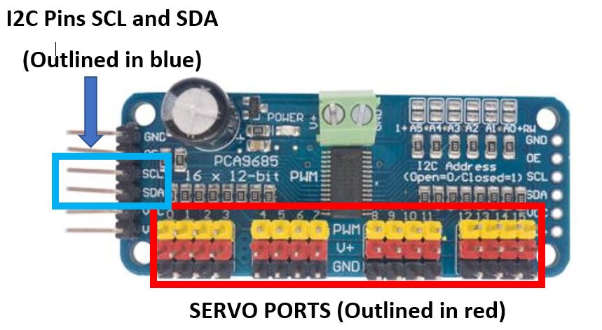
Diagram of Servo Controller pins you will use in this project. Each servo motor has a 3 wire connector. Match the brown servo wire with the black color coded pin in its servo port, match the yellow wire with the yellow pin. Click for larger image.
- Connect the 12 servos to port numbers corresponding to the servo marking (0 to 11). Make sure the signal wire (yellow) is oriented correctly and matches the yellow plastic header pin.
- Connect the switch/battery module regulated BEC output (a three pin Dupont connector where only two of the pins are populated, one with a red V+ wire, one with a black ground wire) to servo controller port 12 power and ground. Make sure the RED wire is going to VCC (red pin) and the BLACK wire goes to GND (black pin).
- On one short side of the Servo Controller you will find a VCC and V+ pin right next to each other. Use a shunt (small black connector that goes over two pins) to connect those together if one is not already installed. This shunt causes both the servos and the microprocessor to run at the same +5V level.
- SDA and SCL go to A4 and A5 on the Nano, respectively.
- Servo port 12 RED and BLACK pins are connected to the output of the BEC. Make sure the BEC RED wire matches with the RED pin, and the BEC BALCK wire matches with the BLACK pin.
- Servo port 13 RED and BLACK pins are connected to the passive buzzer power connector. Make sure the buzzer BLACK wire matches the BLACK pin, and the RED wire matches the RED pin.
- Servo port 14 RED pin goes to a 20cm ORANGE Dupont connector and is routed to the accessory port to provide +5V for sensors or other accessories.
- Servo port 14 BLACK pin goes to a 20cm BROWN Dupont connector and is routed to the accessory port to provide GND for sensors or other accessories.
- Servo port 15 RED terminal goes to a 20cm RED Dupont connector and is routed to the accessory port to provide +5V for sensors or other accessories.
- Servo port 15 BLACK terminal goes to 20cm BLACK Dupont connector and is routed to the accessory port to provide ground for sensors or other accessories.
- Servo port 15 signal terminal goes to 20cm WHITE Dupont connector and is routed to the accessory port to provide signal for a servo used in an optional accessory.
Accessory Port Wire Bundle
The 20cm wires connected to the Nano and Servo Controller provide access to digital ports, analog ports, and power for accessories such as sensors, lights, or other projects. These wires should be bundled up near their unconnected ends (a rubber band works well for keeping them all together) and routed to the large opening below the accessory port hex head screws on the chassis. When there is no accessory in use, these wires can remain tucked inside the accessory port. When needed, pull them out a few inches and connect to sensors or other electrical accessories.
Connecting the HC-SR04 Ultrasonic Rangefinder to the Accessory Port
When building the robot you routed longer jumper wires (20cm) to the accessory port. You need four of these wires to use the Ultrasonic Rangefinder:
- RED accessory port wire goes to HC-SR04 VCC
- BLACK accessory port wire goes to HC-SR04 GND
- GREEN accessor port wire goes to HC-SR04 TRIG
- BLUE accessory port wire goes to HC-SR04 ECHO
The Scratch block assumes you've used this setup.
Connecting the Light Sensor (or any Arduino compatible 5 volt analog sensor)
- RED or ORANGE accessory port wire goes to the center pin, which is usually unmarked (may also be marked +5V, Vcc or Vin) on the sensor
- BLACK or BROWN accessory port wire goes to the ground pin on the sensor, which is usually marked with a minus sign (-) or may be marked GND or G.
- YELLOW (A3) accessory port wire goes to the Signal pin on the sensor. This is often marked (S) but on some sensors may have other markings.
- You may also use PURPLE (A6) for a sensor (or a second sensor)
- The Scratch Sensor block allows you to choose A3 (YELLOW) or A6 (PURPLE) sensor ports.
A note on how many things can be connected through the accessory port
We are providing two sets of power connectors at the accessory port for sensors or other accessories. RED/BLACK and ORANGE/BROWN each respectively provide +5V/GND. It's up to you what things you want to connect using these. You could have one or two sensors, you could have a sensor and some kind off motorized accessory (small motor only!). You could have a sensor and an LED light strip, etc.
Nothing is stopping you from creating a Y connector to make additional power connections, except that there is a limit of 3 amps of current that you can pull from the battery/BEC system. The robot itself needs up to 2.5 amps during fast motions. But many sensors can operate on just a few milliamps. Adding a motorized accessory is where you would need to be careful about how much current you're pulling from the system. If you pull too much current, typically the BEC will overheat and go into thermal protection mode, which will shut down all the motors until you reboot the robot. It is possible to use a mini servo or two under moderate load for a motorized accessory (for example our grip arm add-on kit), but a full sized servo under heavy load would likely be too much. Use caution when designing your own accessories, especially if they are going to use more than a few hundred milliamps of current.
Robot Screw Sizes
- Servo horn screws: 12 x M2.5 by 8mm long
- Switch assembly: 2 x #6-32 by 1/2" long
Electrical Connectons: Gamepad (Bare Bones/Reference)
NOTE: If you have a QuickBuild version of our kit, this information is for reference only. All the connections are already made in QuickBuild kits. This information is for Bare Bones kit builders, self-sourced parts, or if you are an advanced user who may want to add new electrical components or modify the system.
GAMEPAD NANO PIN CONNECTIONS (Bare Bones/Reference)
Diagram of Nano connections for the Gamepad. Click for larger image.
- D2 through D9 are connected to the button matrix pins.Looking from the top of the button matrix module, the rightmost button matrix pin (labeled 1) goes to D9, second to right (labeled 2) to D8, etc.
- D10 to SD card CS (may be labelled SS on some SD card readers)
- D11 to SD card MOSI
- D12 to SD card MISO
- D13 to SD card SCK (may be labelled SCL on some SD card readers)
- A0 Unused
- A1 Dpad OUT (white wire)
- A2 Dpad VCC (red wire)
- A3 Dpad GND (black wire)
- A4 HC05 Bluetooth Module Rx
- A5 HC05 Bluetooth Module Tx
- A6, A7 Unused
- VIN battery/switch positive (red wire)
- GND Either ground on the Nano goes to the battery/switch negative (black wire)
- ICSP pin 4 (see diagram): SD card reader GND. Note: Quickbuild kits do not use this, there's an extra GND wire soldered into the circuit for the SD card reader.
- ICSP pin 6 (see diagram): SD card reader VCC. Note: Quickbuild kits do not use this, there's an extra +5V wire soldered into the circuit for the SD card reader.
- Nano +5V pin goes to HC05 +5V pin
- Nano GND pin (there are two, you can use either one) goes to HCO5 GND pin
GAMEPAD: Screw Sizes
- Gamepad Cover, 4 x #6-32 by 1/2" long
- For kits prior to October 2019: switch adapter assembly, 2 x #6-32 by 1/2" long
Vorpal The Hexapod Quick Links
Getting & Giving Vorpal
